Introduction
As a reminder a simple comparison between SOLID186 and SHELL181 is reported
Mesh
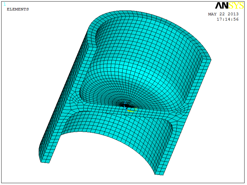 |
SOLID186 Mesh |
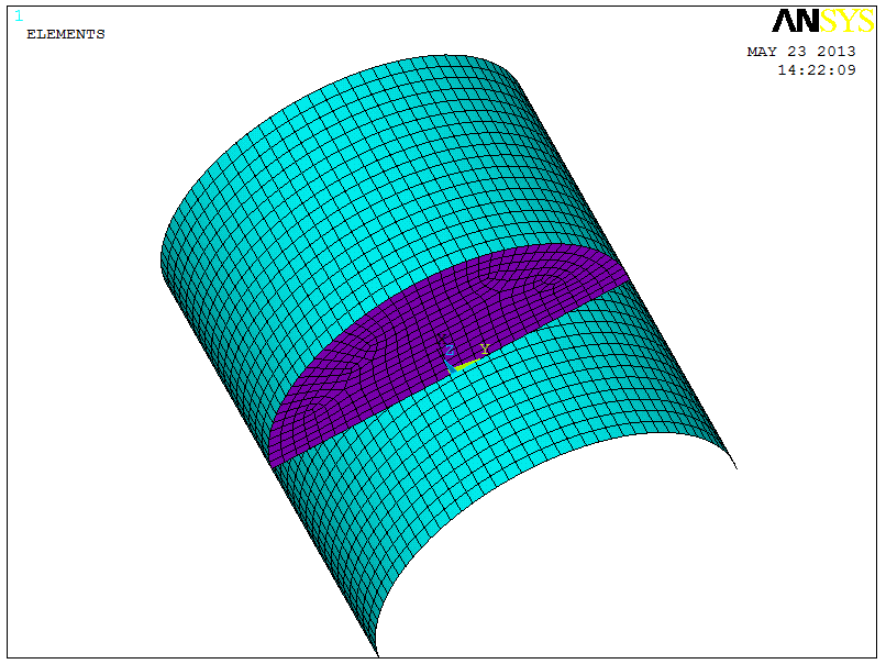 |
SHELL181 Mesh, Surface is loacted at middle-surface of the solid model |
Stresses
The stress result is reported in term of radial stress that can be directly linked to the radial bending moment
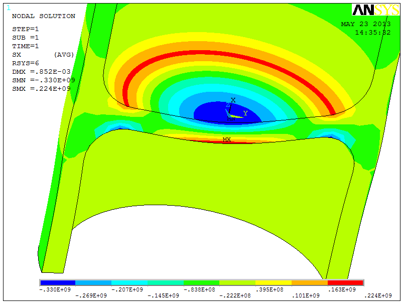 |
Radial stress with Solid |
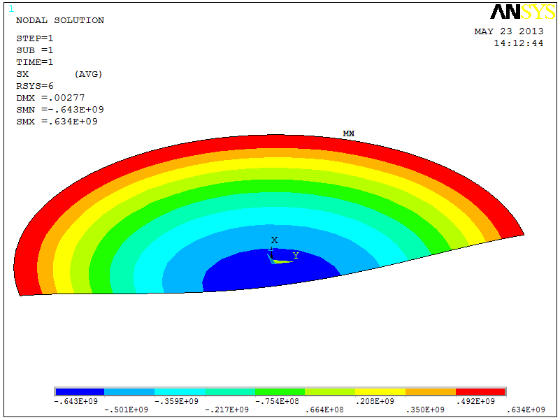 |
Radial stress at Top of SHELL181 |
Comparison
Using Roarke formulas the bending moment at the cilinder surface and at the center of the closing disk can be calculate as a function of the assumed disk radius
| Radius [m] |
Bending at Cilinder [Nm] |
Stress [MPa] |
Bending at Center [Nm] |
Stress [MPa] |
Simply Supported Bending Moment at Center [Nm] |
Simply Supported Stress [MPa] |
| Mean cilinder Radius (0.308) |
263603 |
632 |
171342 |
411 |
434945 |
1043 |
| Inner Cilinder Border (0.285) |
226496 |
544 |
147222 |
353 |
373719 |
897 |
| Start of Fillet (0.22) |
134492 |
323 |
87419 |
209 |
221910 |
532 |
Stress Linearization
Using stress linearizartion it is possible to determine the equivalent bending moment in the SOLID186 section at center and at fillet start. The radial stress behaviour is clearly linear allowing the calculation of the equivalent bending stress.
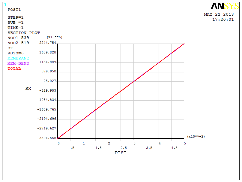 |
Linearized stress at Center section of the SOLID186 Model |
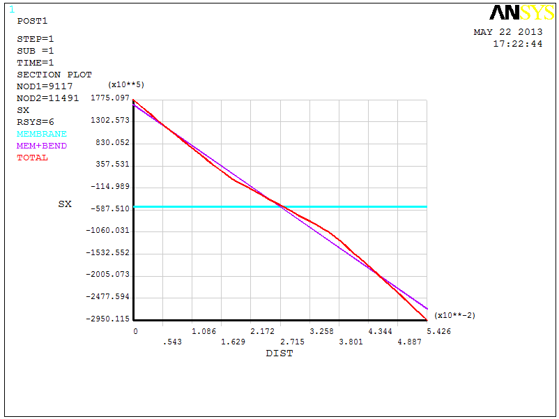 |
Linearized stress at Cilinder surface section where fillet starts of the SOLID186 Model |
The equivalent bending radial stress at the center of the disk
              ** BENDING **  I=INSIDE C=CENTER O=OUTSIDE

      SX          SY          SZ         SXY         SYZ         SXZ

 I -0.2761E+09 -0.2761E+09 -0.1364E+08 -0.6106E-04  0.5699E-04   6018.
 O  0.2761E+09  0.2761E+09  0.1364E+08  0.6106E-04 -0.5699E-04  -6018.
and at the fillet start
              ** BENDING **  I=INSIDE C=CENTER O=OUTSIDE

      SX          SY          SZ         SXY         SYZ         SXZ

 I  0.2195E+09  0.2069E+08  0.1256E+08 -0.9022E+05  0.3692E+05 -0.1102E+08
 O -0.2195E+09 -0.2069E+08 -0.1256E+08  0.9022E+05 -0.3692E+05  0.1102E+08
Summary
For the present geometry the following considerations can be drawn
- the stress of the shell model, at the mean cilinder surface (restrained edge fo the Roarke formulae), is very close to the analytical but much higher than the >SOLID186 model
- stress of the SHELL model, extracted at the inner cilinder surface, is much closer to the bending equivalent of the SOLID186 but still of a order two respect to the latter
- bending stress, at the center of the disk, is inside the range of values for disk radius between the inner surface radius and the fillet start radius for fully restrained edge and
Bottom
--
RobertoBernetti - 23 May 2013


 Create New Topic
 Index
Index
 Search
 Changes
 Notifications
 RSS Feed
 Statistics
 Preferences
